|
The "ADA" Pressure MIT is based on an old water well driller's trick, using an airline to measure fluid levels. As early as 1984, Harold Owens of US EPA Region VII suggested the possibility of using gas to force the fluid level down in certain difficult to test wells in Southeast Kansas. In 1985, tests of the underlying principles were conducted at Kerr Lab in Ada, Oklahoma (hence the name of the test). Beginning in 1986, the "ADA" Pressure MIT was used for certain injection wells located on the Osage Indian lands, a direct implementation (DI) part of the underground injection control (UIC) program administered by US EPA Region VI. Richard C. Peckham and Everett C. Wilson of US EPA Region VI should be given much of the credit for developing this innovative and useful test; they jointly presented a paper, and Wilson published a two part article in Petroleum Engineer.
The "ADA" pressure MIT was originally intended to test the integrity of wells with known casing perforations above the packer. Obviously the conventional standard annular pressure test (SAPT) is of no value in these cases, but the "ADA" Pressure MIT can demonstrate whether other holes exist in the casing above the old abandoned production or injection perforations. For these wells an internal MIT is also required because there could be tubing or packer leaks below the uppermost perforations not revealed by the external "ADA" Pressure MIT; the radioactive tracer survey (RATS) is sometimes used, but if the packer is set 50 feet or more above the injection point, a second "ADA" Pressure MIT is allowed for the internal test. The 50 foot distance was selected to insure adequate pressure differential so a packer leak can be recognized (much less than 50 feet is adequate with the more refined methodology used in the AnaLog Services, Inc. procedure for shallow wells).
In 1990, AnaLog Services, Inc., et al., proposed the procedure described below to US EPA Region IV. On December 21, 1990, Region IV approved our version of the "ADA" Pressure MIT for casing injectors in the Easton and Haynesville fields in Western Kentucky, as an acceptable variant of the pressure test contemplated at 40 CFR §146.8(b)(2) (it has since been used in at least one other Kentucky field). The "ADA" Pressure MIT is a useful, versatile, and surprisingly sensitive test. It actually reveals the location of leaks, something the SAPT cannot do, and during our research we found a well that passed an SAPT, yet failed an "ADA" Pressure MIT! Its ability to distinguish packer leaks, if there is a reasonable distance between the packer and the injection zone, is noteworthy because it can replace the RATS MIT in certain special cases (specifically an application dubbed the "Variant RATS").
See our Sample "ADA" Pressure MIT for an example of an "ADA" Pressure MIT performed on a shallow injection well in Western Kentucky with a data logger.
AnaLog's Suggested Procedure for Shallow, Relatively Low Permeability Wells
1. Determine the injection rate from current records or from water meter 1/10 barrel sweep hand calculations (see Table I). Record the injection rate and injection pressure. It should be noted that the "ADA" Pressure MIT can be used even if a well is not undergoing active injection.
2. Determine the specific gravity (Sg) of the injection fluid. 1000 mg/l (ppm) total dissolved solids (TDS) water will have an Sg slightly less than 1.001, and 10,000 ppm TDS water will have an Sg slightly less than 1.01. The TDS of injected waters in shallow mature waterfloods often falls somewhere between 1000 and 10,000 ppm; hence, 1.005 can be assumed as a reasonable average Sg value for such floods, but for practical purposes 1.0 can be used in many cases.
3. Shut-in the well to stabilize well conditions. Stabilization may take from a few hours to more than two days for wells covered by this suggested procedure. If the pressure fall-off rate can be sufficiently quantified and characterized, it is possible that it can be "factored out" of the "ADA" Pressure MIT results; however, such a process is not normally necessary.
4. Install a gas relief valve on the wellhead during the stabilization period if positive wellhead pressure is expected after said period. An alternative is to manually vent gas from the wellhead immediately prior to commencing the test, but a reliable pre-test pressure reading may be difficult to obtain in this fashion. With either technique, it is essential that the water level be at the surface in positively pressured wells (i.e., no trapped gas) or the actual test pressure will not agree with the calculated test pressure (see Paragraph 6 for exception).
5. For wells with no positive pressure, measure the fluid level in the well with a sounding device (Echometer or equivalent) or with a resistive electric measuring line device. The height of the water column used in the test pressure calculation is the depth to the perforations or injection interval, D, minus the depth to the fluid level, d, or D - d. Wells with positive wellhead pressure are deemed to have fluid at surface if the precautions in Paragraph 4 are followed. There must be at least 200 feet of fluid above the injection zone in wells without positive pressure to proceed with the "ADA" Pressure MIT.
6. Certain wells, not in active use, may have positive wellhead pressure and a depressed fluid level. This presents no problem if the fluid level can be determined without disturbing well equilibrium. Both the water column height and the positive wellhead pressure are used in the formula in such cases. Releasing the trapped gas from this class of well may be possible for some wells, but for others it may disrupt well equilibrium and make it very difficult to calculate the test pressure.
7. Calculate the pressure required to depress the fluid level to the top of the injection zone with the following formula:
Pt = (Hwc x Sg x Gfw x Cg) + Pwh
where:
Hwc is the water column height in the injection well immediately prior to the test (D - d)
Sg is the specific gravity of the fluid to be depressed
Gfw is the pressure exerted by one foot of water with an Sg of 1.0 (.433 psi/ft)
Cg is a correction factor for the mass of different gases that may be used
Pwh is the gauge pressure if a well has positive wellhead pressure
Pt is the calculated achievable test pressure (CATP)
For the shallow wells covered by this suggested procedure, Cg can be assumed to be 1.0 for nitrogen or compressed air, and Sg can often be assumed to be 1.0; therefore, the following simplified formula may apply:
Pt = (Hwc x .433) + Pwh
These calculations have been automated by the authors in a Lotus 1-2-3 template; see Table II for details on obtaining a copy.
8. In the alternative, a small diameter test pipe can be installed in the shallow wells covered by this suggested procedure either temporarily or permanently to accurately determine the test pressure without the use of a fluid level measuring device and without the need to do any calculations. (This is, in fact, the old water well driller's fluid measuring technique on which the "ADA" Pressure MIT is based.) The end of the pipe should be at the top of the injection interval or perforations. 1/2 inch or 3/4 inch polyethylene "coiled black plastic" has been used successfully for this application. The maximum pressure achievable by introducing gas into the test pipe should be identical to Pt (with no need to convert the reading from pounds per square inch to feet). If the test pipe is installed in a well with positive wellhead pressure and sealed with a double tapped bushing or stuffing box, then the maximum pressure reached with gas in the test pipe will automatically include the positive wellhead pressure.
9. Determine the quantity of nitrogen gas required for the test using Table II. A sufficient number of nitrogen cylinders should be on hand to insure that at least 110% of the calculated volume will be available for the test.
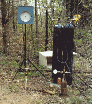
10. Connect a pressure recorder or data logger to the well and record an initial "baseline" pressure for about 15 minutes or until a stabilized trace is evident. The EPA witness (contractor) may initial the paper chart prior to commencement of the test (if a paper chart is used). A pressure recorder or data logger is indispensable in running the "ADA" Pressure MIT on wells covered by this suggested procedure due to the long settling period frequently seen after gas introduction, which effect is believed attributable to the relatively low injection zone permeability in said wells. If possible, the test pressure should be close to 50% of recorder full scale, but certainly should fall within 20-80% of full scale to insure accuracy. Chart recorder rotation should be 24 hours in most cases for wells covered by this suggested procedure. Data logger sampling rates should be on the order of every few seconds to ensure an adequate number of data points (a ten second interval between samples has proven adequate). See this picture of a data logger.
11. Pressure the casing (or tubing) with bottled nitrogen. In low injection rate wells, it is important to depress the water in the injection well at a rate that does not greatly exceed normal injection rates (see Table III). Excessively rapid gas introduction may result in higher than expected pressures, and possible damage to the well. For this reason, a regulator may be used with the pressure set to insure an acceptable depression rate.
12. When pressure at the wellhead will not increase anymore (be sure there is still gas flowing from the cylinder into the well), shut off the valve to the cylinder (see Paragraph 13). The use of a regulator simplifies the determination of whether gas is still flowing into the well by simple gauge observation.
13. In low permeability injection wells, it may be difficult to tell when enough gas has been introduced since a "negative kick" is frequently not seen, and higher than predicted pressures are commonly encountered in these wells during the gas introduction phase of the "ADA" Pressure MIT. (A pressure drop or "negative kick" is normally seen in higher permeability wells when the gas reaches the formation; this effect is believed to be caused by the higher formation permeability to gas versus water.) For wells covered by this suggested procedure, a volume of gas equal to at least 110% of the calculated amount should always be used in the "ADA" Pressure MIT (see Table II).
14. The pressure recorder or data logger should be left connected to the well during the entire "ADA" Pressure MIT procedure, thereby documenting all aspects of the test. It may take several hours for the pressure to settle to the predicted test pressure (CATP) due to the effects of low permeability in the wells covered by this suggested procedure; the length of the settling period may vary greatly from well to well. The use of a chart recorder or data logger eliminates the burden of the witness having to stay at the well for hours (or days).
15. Integrity is demonstrated if pressure declines 0.5% or less in 30 minutes, or 1% or less in one hour after the settling period. EPA Region IV requires an alternative criteria of a water level change of no more than nine (9) feet, or 3.9 psi, in one hour (formerly 2.2 psi). The settled test pressure must be reasonably close to the calculated achievable test pressure (CATP) with appropriate allowances for uncertainties in the values used for the calculation. A settled test pressure higher than the CATP is of course of less concern than one lower.
16. Failed "ADA" Pressure MITs can be interpreted as follows:
A. If the fluid level is below surface and no pressure can be developed in the well, then a leak exists in the tubing or casing above the fluid level.
B. If the calculated pressure cannot be obtained, then a leak exists in the tubing or casing between the fluid level and the injection zone.
C. If the calculated pressure is reached or exceeded and the pressure decreases below the calculated value during the settling period, a small leak exists above the injection zone.
The depth to a leak can be calculated using the following formula:
Dleak = (Pf ÷ Sg ÷ Gfw) + d
where:
Pf is the pressure achieved in the failed test (less Pwh)
Sg is the specific gravity of the well fluid
Gfw is the pressure gradient of fresh water or .433 psi/ft
d is the depth to fluid prior to the test
Dleak is the depth to the tubing or casing leak
DISCLAIMER
This Suggested Procedure is furnished as is, without warranty of any kind, either express or implied. We shall not be liable to any person or entity with respect to any loss or damage caused, or alleged to be caused, either directly or indirectly by use of or reliance on this material.
The "ADA" Pressure MIT involves the use of high pressure gas. High pressure gas is dangerous stuff; do not attempt the "ADA" Pressure MIT if you are not familiar with high pressure gas safety rules, procedures, and practices. DO NOT USE OXYGEN as the high pressure gas for any MIT.
AnaLog Services, Inc. and Kenneth R. Ingle Associates, Inc.
| Home | Tech & Tips | MIT Menu | Table I | Table II | Table III | Sample "ADA" |
06-00
Last 10-20-10
|
|